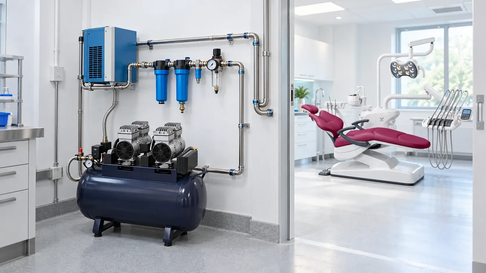
A compatible dental air system starts with the dental unit data sheet. Record the required inlet pressure, air consumption, connection, air-quality condition, and permitted operating range for every unit before comparing compressor models. The selected oil-free compressor must then deliver enough usable air at that pressure after dryers, filters, regulators, and distribution losses are considered.
This is a unit-to-system matching task. Clinic-wide capacity planning is a related but broader calculation. Gladent’s dental unit procurement guide places compressed air within the full operatory utility plan; the checklist below concentrates on the interface between the compressor system and the dental units it serves.
Create one line for each dental unit configuration in the project. Do not assume that two models from the same supplier use identical air conditions. Options such as air-driven suction, additional handpiece positions, or a portable delivery system may change the load or connection arrangement. For a repeat order, check the current approved configuration rather than copying an old model name.
If a specification is missing, ask the dental unit supplier to confirm it in writing. Compressor horsepower, tank volume, and a claim such as supports four chairs are not substitutes for this unit-side information.
The pressure shown on a compressor gauge is not necessarily the pressure available at a dental unit. Air loses pressure across dryers, filters, regulators, fittings, long pipe runs, undersized tubing, and simultaneous demand. Compare the dental unit requirement with the minimum pressure expected at the most remote or most demanding operatory while the design load is running.
The compressor control range and dental unit inlet requirement also serve different purposes. The compressor may store air at a higher pressure, while a regulator reduces it for the distribution system or the equipment inlet. Confirm the permitted pressure at every downstream component. Excess pressure can create noise, leakage, premature wear, or incorrect instrument performance; low pressure can reduce handpiece performance and make controls inconsistent.
Add the air consumption of the dental units and accessories that can operate at the same time. Use delivered airflow at the required pressure, not only pump displacement or a free-air figure without test conditions. Keep units consistent when comparing CFM and L/min, and ask the supplier to state the pressure, temperature, and measurement basis behind the rating.
A receiver tank supplies a short buffer and reduces rapid cycling, but it does not correct insufficient continuous output. Likewise, an unexplained safety factor can hide a weak calculation. Document the simultaneous-use case, pressure-loss allowance, leakage allowance, and any planned expansion so the buyer can see why the recommendation was made.
Oil-free compression removes one potential contamination source from the compression chamber. It does not by itself confirm that air reaching the dental unit is dry, clean, or suitable for the project. Moisture may enter at the intake and condense after compression, while particles can come from filters, receivers, piping, or installation debris.
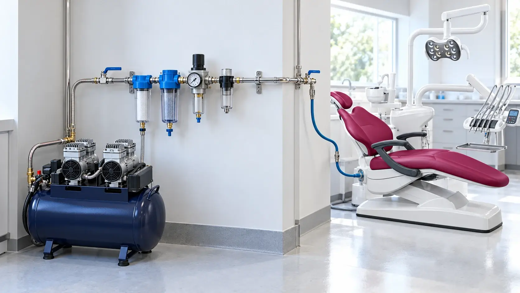
Map the complete path from intake to dental unit: compressor, aftercooling or separator, dryer, receiver, drains, filters, main line, branch line, regulator, shutoff valve, flexible connection, and any point-of-use filter. For every treatment stage, request the rated flow, pressure drop, service interval, replacement element, drain method, and operating limits.
When a project specifies central dental compressed-air source equipment, ISO 22052 can be a useful standards reference. The responsible designer or installer must still confirm the applicable edition, local adoption, and project requirements.
A correct pressure and flow calculation can still fail at the connection. Confirm the branch pipe material and diameter, route length, number of bends, valve locations, flexible hose specification, and fitting standard. The installer should calculate pressure loss for the actual layout and avoid materials or sealants that could contaminate the air stream or conflict with local requirements.
Provide an accessible shutoff for each operatory or defined branch so a dental unit can be serviced without disabling the whole clinic. Label branches and keep the final layout with the equipment record. For multi-unit projects, this documentation also helps technicians distinguish a compressor problem from a blocked filter, maladjusted regulator, leak, or restricted branch line.
The quotation should state where the compressor supplier’s responsibility ends and the installer or project contractor takes over. Confirm who supplies the dryer, filters, receiver, regulator, electrical protection, isolation valve, pipework, condensate drain, vibration control, enclosure, ventilation, and commissioning instruments.
Check voltage, frequency, starting current, circuit protection, ambient-temperature range, ventilation, floor loading, door access, service clearance, intake-air location, and noise transfer. Keep the intake away from exhaust, chemical storage, contaminated spaces, and excessive heat or moisture. A compact mechanical room is not useful if filters cannot be changed or a motor cannot be removed safely.
Commissioning should verify the assembled system rather than the compressor alone. Test static pressure, then measure pressure at representative dental units under the agreed simultaneous-use case. Record compressor cut-in and cut-out behavior, recovery, excessive cycling, regulator settings, leaks, drains, dryer operation, and any alarms.
At the dental unit, check for stable instrument performance and confirm that inlet pressure remains within the manufacturer’s range. Flush and clean the new distribution system as required before connecting clinical equipment. Keep baseline readings, valve locations, filter references, and commissioning results with the maintenance record so later changes can be investigated against known conditions.
Send suppliers the dental unit schedule, quantity, destination market, simultaneous-use case, required point-of-use pressure, unit air-consumption data, pipe distance, elevation differences if relevant, electrical supply, room conditions, air-treatment requirement, noise constraint, and future expansion plan. Ask each bidder to return the same technical fields and identify every assumption.
Gladent lists dental units, oil-free air compressors, suction equipment, handpieces, curing lights, and related accessories within its dental equipment range. Buyers should request current product data for the exact compressor and dental unit combination rather than assuming compatibility from the shared brand or catalog category. The product center can help define the chair configuration before the RFQ is issued.
Match the dental unit first, then verify the whole air path. Required inlet pressure, simultaneous airflow, pressure loss, air treatment, connections, installation conditions, and commissioning results must agree as one system. A tank size or chair-count claim cannot replace that compatibility check.
For a project review, send the dental unit models, quantities, utility drawing, destination electrical supply, operating schedule, pipe route, and required air-treatment scope, then contact Gladent for a configuration-specific quotation.
It can be higher upstream if the complete system is designed for it and a suitable regulator reduces pressure before the dental unit. Confirm the permitted pressure of the receiver, dryer, filters, piping, regulator, hose, and dental unit rather than relying on one gauge.
No. A larger receiver can cover short peaks and reduce cycling, but continuous demand still depends on delivered compressor output at the required pressure.
The correct arrangement depends on the equipment instructions and system design. Accessible branch isolation is useful for service, and regulation should keep each dental unit within its specified inlet range. The project designer should confirm the final layout.
Record static and loaded pressure at representative dental units, simultaneous-use performance, compressor cycling and recovery, regulator settings, leaks, dryer and drain operation, alarms, and baseline service information.
 No. 1, No. 2, Fenggang Industrial Zone, Lianhe, Luocun, Shishan Town, Nanhai District, Foshan City, China
 Call us now:+86-757-81267151