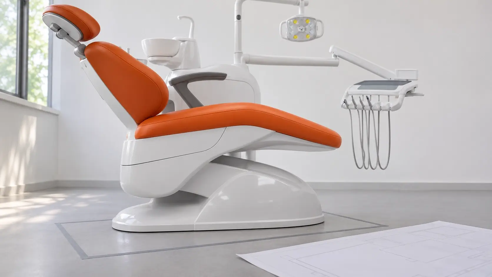
A dental chair plumbing diagram should prevent site rework, not merely show that water and suction are required. For a new clinic, renovation, or chair replacement, the useful document is a model-specific utility drawing that locates every connection relative to the chair base, floor, cabinetry, and service zone. It should arrive before the contractor drills, pours, closes the floor, or fixes the cabinets.
Generic diagrams found online can help teams understand common systems, but they are not installation instructions for a purchased unit. Connection positions, clearances, pressure ranges, electrical requirements, and drain arrangements vary by model and configuration. The buyer’s job is to obtain the current drawing, coordinate it with the room plan, and make each party sign off on the same revision.
A diagram from another model can place the service box on the wrong side, assume a different delivery layout, or omit an option that changes routing. Even drawings for the same product family may differ by production revision or local configuration. Treat any generic plan as a discussion aid only. The approved drawing should identify the model, configuration, drawing number, revision date, units of measurement, orientation, and required tolerances.
The room plan and the equipment drawing also answer different questions. The room plan shows walls, doors, cabinetry, circulation, and the intended chair position. The equipment drawing shows the chair’s connection and anchoring needs. Overlay them at the same scale. A connection can be correct relative to the chair yet still conflict with a cabinet base, floor beam, access panel, or assistant working zone.
Start with the Gladent product center and the Integral Dental Unit catalog to identify the exact dental unit. If the shortlist includes the GD-S200 Plus integral dental unit, ask Gladent for the current pre-installation drawing and configuration list for the quoted version. Product-page photographs are useful for orientation, but they cannot confirm concealed connection coordinates or site requirements.
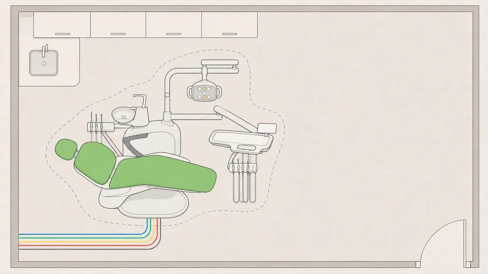
The drawing package should state which utilities are supplied by the building and which components arrive with the dental unit. It should also separate pre-installation work from final assembly and commissioning. Ask who is authorized to install, connect, test, and sign off the unit in the destination market. This avoids a common gap in which every party assumes another contractor will supply a valve, adapter, cable, or drain fitting.
Verify the chair centerline, base outline, rotation or movement envelope, entry side, and final patient orientation. Mark the approved reference point on the construction plan. Confirm the floor structure and approved anchoring method with the equipment supplier and a qualified local contractor. Do not copy anchor positions or structural assumptions from another model.
The drawing should locate the water and air connection points and identify any required shutoffs, regulators, filters, or service box. The supplier should confirm acceptable pressure and quality ranges for the ordered unit. The contractor should confirm local pipe materials, backflow controls, isolation strategy, and how lines will be flushed before connection. Place manual shutoffs where technicians can reach them without moving the chair or dismantling cabinetry.
Separate the dental unit’s connection requirement from the clinic’s central vacuum design. Line sizing, slope, venting, separation equipment, and pump selection belong to qualified designers and local requirements. The unit drawing still needs to show the connection location, permitted routing zone, interface size, and access needed for inspection. Confirm how bowl drainage and suction lines are distinguished so the contractor does not combine unlike connections.
Confirm voltage, frequency, circuit, protective device, grounding or earthing, disconnect location, and cable entry for the exact unit. Ask whether accessories add loads or require separate supplies. Electrical work must follow the manufacturer’s instructions and applicable local rules. Keep power routing coordinated with wet services, service access, and movable chair components.
Draw a service zone around valves, filters, traps, connection boxes, and removable covers. Then check that cabinetry, flooring transitions, and mobile equipment do not occupy it. The same area should be cleanable after installation. A technically correct connection becomes a maintenance problem when a technician cannot see it, place a tool on it, or isolate it quickly.
Use the site-planning section of the dental unit procurement guide to connect the equipment decision to the RFQ and construction schedule. Hold one coordination review with the buyer, dental unit supplier, contractor, electrician, plumber, and cabinet or interior team. Record every open item on a responsibility matrix with an owner and due date.
Issue a marked-up overlay showing the approved chair position and each utility stub-up. Require written acceptance before irreversible work. If the model, handedness, delivery arrangement, cuspidor position, cabinetry, or room orientation changes, stop and reissue the drawing. A verbal instruction should never override the approved revision.
Before releasing the room for installation, confirm that:
The site’s dental chair installation guide explains the broader sequence, while the installation and maintenance guide provides useful follow-through after setup. For this plumbing-focused handover, require leak checks, pressure and flow checks where specified, suction and drainage tests, electrical safety checks by qualified personnel, full chair movement tests, and verification that no hose, cable, or cover is pinched or obstructed.
Photograph the completed connection area before covers are closed. Store the approved drawing, commissioning record, serial and configuration information, installer details, and staff training record together. Record any approved deviation on an as-built drawing. These documents make future troubleshooting faster and help distinguish equipment faults from building-utility problems.
The most expensive errors usually occur before installation: ordering the room around a generic chair outline, fixing cabinets before service access is checked, locating a shutoff under an immovable base, or letting several trades work from different drawing revisions. Another frequent mistake is asking the equipment supplier to design the entire building system. The supplier should define the unit interface; qualified local professionals should design and approve the building-side work.
A useful dental chair plumbing diagram is a controlled, model-specific construction document. It aligns chair position, utility interfaces, access, and responsibilities before irreversible work begins. Obtain the current drawing from the supplier, overlay it with the room plan, review it with every trade, and commission the installed unit against the same revision. That process is more valuable than any generic set of connection dimensions.
Only for early discussion. Final construction should use the current drawing for the exact model and configuration, coordinated with the room plan and local requirements.
Approve it before drilling, concrete work, floor closure, or fixed cabinetry. Reissue it whenever the equipment configuration or room orientation changes.
The dental unit supplier defines the equipment interface and model requirements. Qualified local professionals design and approve the building-side plumbing, electrical, vacuum, drainage, and structural work.
Keep the approved and as-built drawings, configuration and serial records, commissioning results, installer contacts, training records, warranty documents, and any approved deviation notes.
 No. 1, No. 2, Fenggang Industrial Zone, Lianhe, Luocun, Shishan Town, Nanhai District, Foshan City, China
 Call us now:+86-757-81267151